Design requirements for 5/10-ton crane beam in portal frame
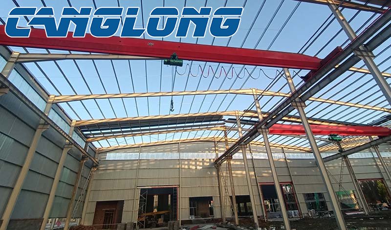
Introducing a 5-ton or 10-ton crane into a portal frame steel structure means that the structure must not only withstand dead loads and wind/snow loads, but also the longitudinal and lateral horizontal braking forces, dynamic vertical wheel pressure, and vibration impact loads from the crane.
5-ton and 10-ton cranes are considered small to medium tonnage cranes, typically using ordinary suspended cranes or cantilevered beam cranes. To ensure system safety and durability, the connection design of its support (cantilever), crane beam, and main frame (columns and beams) must strictly meet the following mechanical and structural requirements.
I. Core Stress Analysis and Stiffness Requirements
Before designing the connections, the load characteristics of the 5-ton and 10-ton cranes must be clearly defined:
Dynamic Coefficient: When calculating vertical loads, a dynamic coefficient (usually 1.1-1.3) must be multiplied to offset the impact of the crane lifting.
Material Threshold: The load-bearing main columns and brackets must be made of Q355B grade high-strength steel to provide sufficient shear and bending stiffness and prevent local buckling.
Stiffness Control (Deformation Limitation): The vertical deflection limit of the crane beam is usually L/400 (L is the crane beam span).
The lateral displacement limit of the column top under the horizontal force of the crane is usually H/400 (H is the column height).
II. Connection Design of Brackets and Steel Columns
The bracket is a skeletal protrusion that bears the vertical wheel pressure of the crane beam, transferring the enormous shear force and bending moment to the main frame column.
Welding and Section Construction Requirements
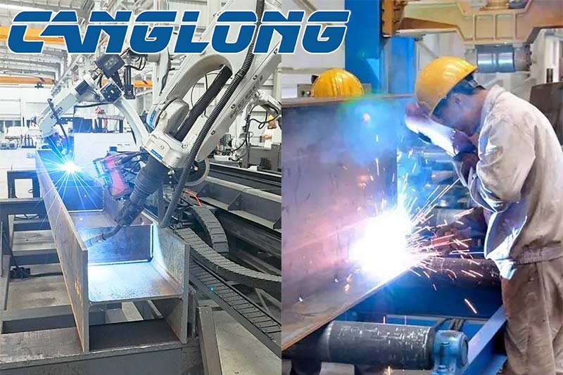
Full Penetration Welding: The upper flange (bearing tensile force) and web (bearing shear force) of the corbel must be connected to the flange of the rigid frame column using Class I or Class II full penetration butt welds. Ultrasonic non-destructive testing (UT) is mandatory; ordinary fillet welds are strictly prohibited.
Stiffening Rib Installation: Transverse stiffening ribs must be installed inside the rigid frame column, directly opposite the upper and lower flanges of the corbel. Their thickness should be no less than the thickness of the corbel flange to transfer tensile and compressive stresses and prevent local buckling of the web of the steel column flange.
Shear Key: For 10-ton cranes, due to the large vertical shear force, a shear support plate (shear key) can be welded below the connection between the corbel and the column to share some of the shear force and reduce weld fatigue.
Crane Beam Welding
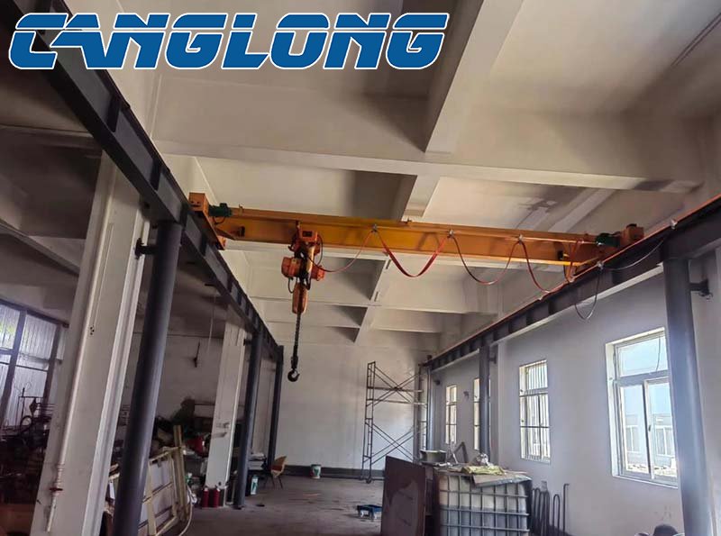
III. Crane Runway Beam and Corbel Connection Design
The crane runway beam rests on the corbel. The connection must employ a structural logic of vertical rigid connection to transmit wheel pressure, with horizontal quasi-free movement, to release longitudinal stress caused by temperature changes.
1. Vertical Connection (Beam Bottom and Corbel Surface)
Flange Support and Bolt Anchoring: The crane runway beam end is typically designed as a flange support, connected to the upper surface of the corbel using M20 or M24 high-strength bolts (grade 10.9).
Slot Holes: To adjust for installation errors and release axial stress caused by longitudinal braking force or temperature changes, the bolt holes in the corbel or crane runway beam bottom plate are typically elongated longitudinally.
Planking and Tightening: The contact surface between the load-bearing support plate at the crane runway beam end and the lower flange must be planed and tightened to ensure that the enormous vertical wheel pressure is directly transmitted to the corbel through direct contact (contact force transmission), rather than relying solely on bolt shear resistance.
2. Upper Flange Lateral Connection (Side Force Resistance Connection)
When a crane starts and brakes, it generates a large lateral horizontal force (T-Force), which must be directly transmitted to the steel column.
Tension-Compression Plate: A lateral connection plate must be installed between the upper flange of the crane beam and the steel column.
Construction Details: This connection plate is typically made of flat steel or angle steel, welded to the steel column, and connected to the crane beam flange using high-strength bolts. This connection plate must possess a certain degree of vertical flexibility (allowing for slight deflection of the crane beam) but extremely high horizontal stiffness to directly pull the lateral thrust into the main frame column.
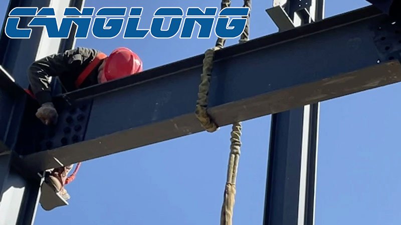
Connection Between Bracket and Main Beam
IV. Specialized Fatigue and Loosening Prevention Structures for 5-Ton/10-Ton Systems
The most critical factors in industrial crane connection design are fatigue failure and bolt loosening. 5-10 ton cranes are classified as medium-duty (A4-A5 level) and must adhere to the following construction standards:
Rail Plate Connection: Crane rails (e.g., P24 or P38 rails) must never be welded to the upper flange of the crane beam. Composite pressure plates with rubber pads (adjustable pressure plate system) must be used. The rubber pads absorb crane vibrations and reduce fatigue impact on the weld joints.
Double Nuts or Anti-Loosening Washers: All high-strength bolts connecting the crane system must be equipped with double nuts for anti-loosening or use friction-type high-strength bolts. Contact surfaces must be sandblasted or shot-blasted, with an anti-slip coefficient ≥0.45. Ordinary bearing bolts are strictly prohibited.
Vertical Bracing System (X-Bracing): In the spaces between columns where crane beams are installed, robust inter-column bracing must be installed longitudinally (especially the lower column bracing below the crane beam). The longitudinal braking force of the crane is transmitted through the crane beam to the supporting column, and then from the support to the foundation, forming a complete closed-loop mechanical transmission path.
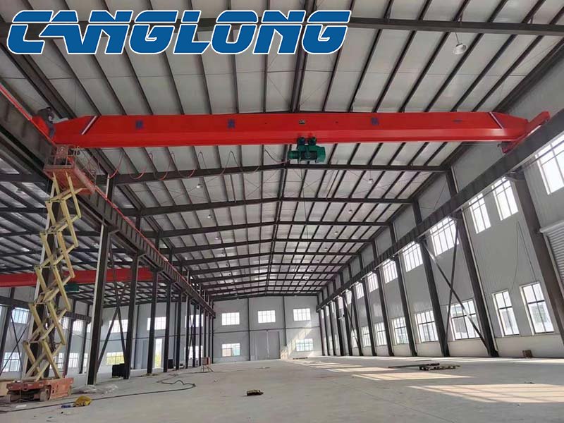
Portal Frame Workshop with Crane
Canglong Group's Digital One-Stop Delivery Standard
In the cross-border export project of a gantry crane factory, Canglong Group achieved the above requirements to the extreme through BIM (Building Information Modeling) and a fully automated manufacturing system:
3D Collision and Detailing: Every high-strength bolt hole and internal stiffening rib location of the crane beams, corbels, and main columns is simulated 1:1 using BIM before leaving the factory, ensuring zero hole enlargement and zero cutting on-site overseas.
Automated Robotic Welding: The full penetration butt welding of the corbels and H-beam columns is uniformly completed by industrial-grade robots. The weld fullness and UT (Understanding Test) pass rate meet the highest international public safety standards of ASTM/CE, completely eliminating structural safety hazards caused by the lack of highly skilled welders overseas.
Latest News
-
Why sandwich panels are the fastest-growing building envelope solution?
-
How the pre-engineered building market is reshaping industrial space
-
Why are PU panels the preferred choice for factory construction in Thailand?
-
How to build a three story office building in the Philippines in 30 days?


