Metal-faced pu sandwich wall panel installation guide
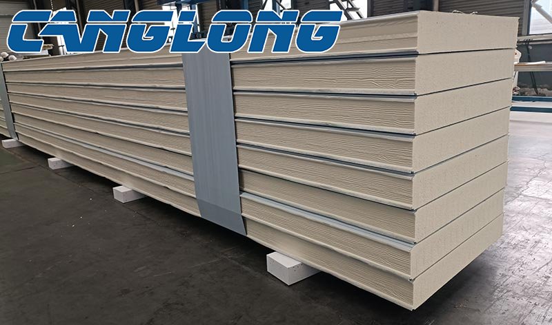
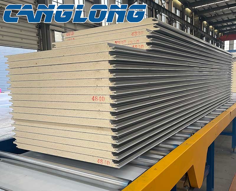
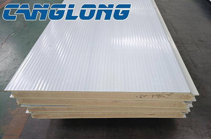
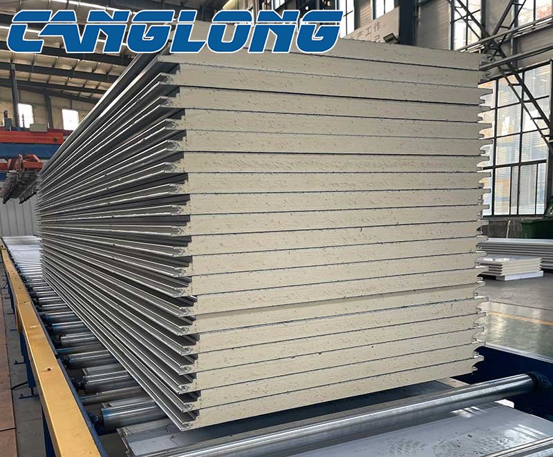
In the construction industry, metal-faced PU sandwich wall panels have become the preferred material for exterior and interior walls in industrial plants, logistics warehouses, commercial complexes, and residential buildings due to their lightweight, high-strength, thermal insulation, fire and moisture resistance, and quick installation.
The composite structure of metal panels and polyurethane core material can adapt to diverse climate requirements, whether for low-energy buildings in the cold climates of North America or industrial plants in the humid and hot climates of Southeast Asia. This article will systematically explain the standardized installation process for metal-faced PU sandwich wall panel based on international standards and global construction practices, helping construction professionals complete projects efficiently.
I. Pre-Installation Preparation
The installation performance of metal-faced PU sandwich wall panel is directly related to the pre-installation preparation. Rework due to overlooking site conditions or discrepancies in standards is common on projects, so the following tasks should be prioritized:
1. Material and Tool Verification
Core Materials: Confirm the wall panel specifications, typically 50-200mm thick and 600-1200mm wide, consistent with the design drawings. Verify that the panel (galvanized steel/aluminum-magnesium-manganese alloy) is free of scratches and that the core material (polyurethane density ≥ 40kg/m³) is free of damage or moisture (humidity > 60% requires moisture-proofing).
Supplementary Materials and Accessories: Select materials based on the regional climate. For example, in high-humidity regions, use a weather-resistant sealant (compliant with ASTM C920), while in cold regions, use a frost-resistant sealant. Ensure the wall thickness of the studs (aluminum alloy/galvanized steel) is ≥ 1.2mm. Ensure that the anchors (self-tapping screws/expansion bolts) match the base material (concrete/brick wall/light steel structure).
Tool List: Required: Laser level (accuracy ±0.5mm/m), electric drill (with metal drill bit), plasma cutter (for cutting wall panels into special shapes), torque wrench (for controlling screw tightening torque), and air nail gun (for temporary fixing).
2. Confirming Site Conditions
Substrate Preparation: The wall surface must be flat (accuracy ≤ 5mm/2m), dry (moisture content ≤ 10%), and free of oil stains or loose layers. If the substrate is concrete, a primer should be applied to enhance adhesion. If the substrate is a lightweight steel structure (such as a C-channel), purlins must be installed and leveled first (spacing ≤ 600mm).
Climate Adaptation: In tropical regions, avoid construction during the rainy season (operation should be suspended if humidity exceeds 85%). In cold regions, ensure the ambient temperature is >5°C. If the temperature drops below this, the substrate should be heated to above 10°C to prevent adhesive failure.
Compliance Check: Verify local building codes (such as the US IBC fire rating and the EU EN 14509 fire standard) to confirm that the wall panel fire rating (typically B1-B2) meets design requirements. Industrial projects require additional verification of wind load resistance (≥0.5kN/m²) and seismic performance.
II. Core Installation Process
Phase 1: Frame System Installation
Frames are the "skeleton" of the wall panel, and their installation accuracy directly impacts the panel's flatness and wind resistance. In global projects, frame installation procedures for lightweight steel structures and concrete subgrades differ slightly:
Lightweight Steel Subgrade:
①. Secure the main purlins (C-channel or H-beam) at the designed spacing (typically ≤600mm), ensuring a straightness error of ≤3mm/10m.
②. Install secondary purlins (aluminum alloy square tubes or galvanized square steel) on the main purlins. Connect the secondary purlins to the main purlins with stainless steel self-tapping screws (spacing ≤ 300mm) to form a "well"-shaped support.
③. After the secondary purlins are leveled, use a spirit level to verify. Any local deviation greater than 2mm requires adjustment with stainless steel shims.
Concrete/brick wall base:
①. Draw a horizontal reference line (1.2m from the ground) and mark the keel fixing points, spacing them ≤ 600mm.
②. Use expansion bolts (8-10mm diameter, ≥ 50mm length) to secure the galvanized keel (≥ 1.0mm thickness). The drilling depth should exceed the bolt length by 20mm to avoid damaging the base structure.
③. When extending the keel, use specialized connectors. Install the joints with staggered joints (gap ≤ 2mm) and fill with sealant.
Key Tips: During a project, the connection between the keel and the main structure must account for thermal expansion and contraction. It is recommended to leave 5-8mm expansion joints at both ends of the keel and fill them with silicone sealant to prevent deformation due to temperature fluctuations.
Phase 2: Wall Panel Lifting and Positioning
Metal-faced PU sandwich wall panels are lightweight (approximately 15-30kg/m²) and can be handled manually or with the assistance of a small crane. The installation sequence should be from left to right and top to bottom to avoid cross-working and scratching the panels:
①. Pre-layout Test Installation: The first wall panel should be installed along the reference line. Check the panel joint width (typically 10-15mm) and the tongue-and-groove fit (the overlapping edge of the metal panel must fully fit into the groove on the other side). Adjust the keel position until the tolerance is ≤2mm.
②. Temporary Fixing: Use an air nail gun (nail spacing ≤300mm) or adjustable clamps to temporarily secure the top and sides of the wall panel to prevent it from tipping over. Large-sized wall panels (width > 1200mm) require the coordinated operation of at least two people to avoid deformation caused by unilateral force.
③. Permanent Fixing:
Screw Fixing: Drill holes at the panel's peak (or designated design location). Use self-drilling screws (4.2-5.5mm diameter, ≥ 25mm length) to penetrate the panel and core material, and secure to the studs. The screws should be sunk 1-2mm into the panel, and the anti-rust caps should be flush with the panel to prevent water penetration.
Structural Adhesive Assistance: In areas with high wind pressure (such as coastal areas), apply weather-resistant sealant (≥ 8mm width) around the panel joints and screws to provide both mechanical fixation and a sealed seal.
Avoidance Tips: Do not drill directly into the PU core material. Ensure that the screws penetrate only the metal panel. If the panel is coated, fill the holes with sealant after drilling to prevent coating loss and water absorption into the core material.
Phase 3: Joint Treatment
Wall panel joints are prone to water seepage and cold bridges, requiring a standardized four-step process: cleaning, caulking, sealing, and protecting.
①. Cleaning: Use a brush or compressed air to remove dust and oil from the joints. Ensure the joint depth is ≥10mm. If insufficient, remove some of the core material.
②. Caulking: Fill with polyurethane foam (density ≥35kg/m³). Ensure a slight overflow from the joint. Avoid overfilling, which may cause bulging. For cold regions, use low-temperature-resistant foam (resistant to cracking at -40°C).
③. Sealing: After the foam has cured (approximately 24 hours), remove any excess (leaving a 2-3mm deep groove). Fill with weather-resistant silicone sealant (color coordinated with the panel surface). Use a sealant gun to evenly squeeze the sealant to form a continuous, smooth strip (≥8mm wide).
④. Protection: After sealing, apply PE protective film, covering 100mm on each side of the panel joint to prevent contamination from subsequent construction. Do not touch the joints for 24 hours.
Adaptation Tips: In tropical, rainy regions, a combination of external sealant and internal waterproof, breathable film (film thickness ≥ 0.1mm) can be used. This prevents liquid water from penetrating while allowing moisture from the core material to escape, preventing condensation and moisture. In cold regions, the joints should be thicker (≥ 12mm) and a crack-resistant elastic sealant (elongation ≥ 300%) should be used.
Phase 4: Finishing and Acceptance
After installation, both a visual inspection and functional testing are required to ensure there are no potential problems.
Visual Inspection: Ensure the panel surface is free of scratches or dents, the joints are straight (≤ 2mm tolerance), the sealant is free of bubbles or cracks, and the metal panel has a uniform color and is free of oxidation discoloration.
Functional Testing:
Airtightness: Use a tracer gas detector (such as SF₆) according to ISO 9972, with an air change rate of ≤0.5 times per hour (for industrial buildings) or ≤1.0 times per hour (for residential buildings). v Wind-blowing Resistance: Select 5% of the panel joints and test them in a negative pressure chamber (negative pressure ≥ 0.5 kPa) to inspect the sealant and screws for loosening. No noticeable movement is considered acceptable.
Fireproofing: Randomly sample samples and conduct a combustion test according to EN 13501-1 or GB 8624 to confirm that the combustion performance meets the design level (e.g., Class B1 flame retardant).
III. Common Project Problems and Solutions
1. Problem: Core material expands due to water absorption in humid areas
Cause: Inadequate joint sealing or lack of a moisture-proof base layer.
Solution: Apply a waterproof coating (such as cement-based penetrating crystallization) to the base layer before installation. Add butyl tape (width ≥ 15 mm) to the joints. Install a water channel (slope ≥ 3%) under the panel.
2. Problem: Condensation caused by thermal bridges in cold regions
Cause: The keel is in direct contact with the main structure and no thermal insulation is provided.
Solution: Install thermal insulation gaskets (such as EPDM rubber pads, thickness ≥ 5mm) between the keel and the concrete/steel structure, or fill the keel with polyurethane foam (density ≥ 40kg/m³).
3. Problem: Wall panels flipped in typhoon areas
Cause: Insufficient anchors or excessive spacing.
Solution: Increase the screw density according to wind resistance design specifications (e.g., in coastal wind zones with force 12, screw spacing ≤ 200mm), and add an L-shaped capping strip at the top of the wall panel, welded to the main structure.
Conclusion
The advantages of metal-faced PU sandwich wall panels can only be fully realized through standardized installation. From preliminary planning to final acceptance, meticulous attention to detail at every stage directly impacts the durability, safety, and energy efficiency of a building. Construction practitioners must adapt their processes to local regulations and environmental characteristics, ensuring that each wall panel becomes a breathable, weather-resistant, and energy-efficient building skin.
Latest News
-
Canglong steel structure solution for a 5000㎡ factory in Chile
-
Advantages of metal surface insulated sandwich panels for steel plants
-
How to achieve 95% material recyclability in steel structure buildings?
-
How can steel truss and H-beam reshape the internal space limit of warehouses?


